The URI sound source
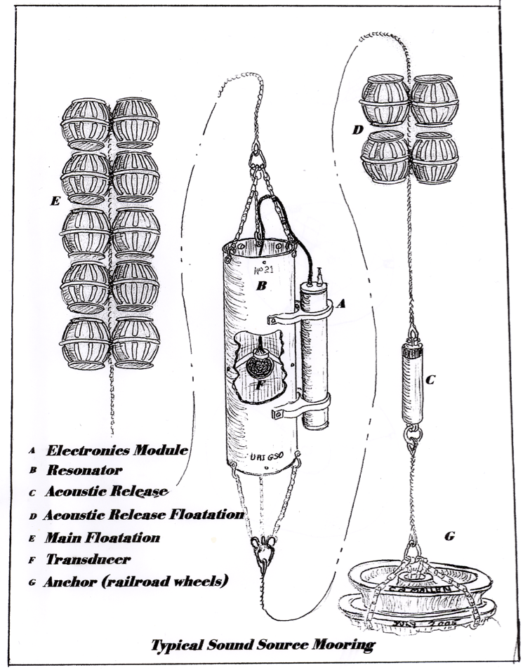
We developed this sound source a little over 20 years ago. It was a joint project between me and Prof. Jim Miller in the URI Ocean engineering Dept. It is pretty much the standard sound source for all RAFOS navigation applications. It consists of an open aluminum tube, 0.4 m diameter, 1.78 m long and with a 1.27 cm thick wall. Mounted its center sits a 15 cm diameter piezo-electric monopole transducer that vibrates radially with a center frequency of 262 Hz. These vibrations set up resonant pressure oscillations that radiate primarily horizontally away from the tube. We have calibrated the sound source several times, and find that with 1000 VAC applied to the monopole the radiated source level will be 180 dB re 1 μbar @ 1 m. It is very efficient – 100% (as defined, meaning if the sound pressure level in the horizontal plane were the same in all directions). But it also has a Q of about 100, meaning that its 3 dB bandwidth is barely 3 Hz. This means that the tube length must be adjusted so it will resonate at the local speed of sound where it is to be deployed. The design is of course scalable to other frequencies. The latest version of the sound source has a SeaScan clock that is accurate to within 1-2 seconds per year. The sources are now built at the Woods Hole Oceanographic Institution.
Yvette
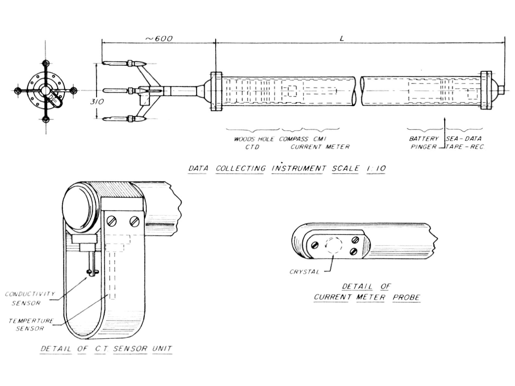 Evans, D., H.T. Rossby, M. Mark and T. Gytre. YVETTE-a free fall shear profiler. Deep-Sea Res., 26, 703-718, 1979.
Schematic view of Yvette. The sensors at the lower end consist of a pair of orthogonal Trygve Gytre acoustic current meters, and a Neil Brown CTD. As it sinks the current meters measure velocity relative to average motion of the near 6 m long tube. Dave Evans developed an inverting algorithm to estimate vertical shear to scales roughly 10x greater than the instrument. Knowing shear and density gradient we can determine the Richardson number from about .5 to 50 m in the vertical, a very useful range of scales.
The Pegasus profiler
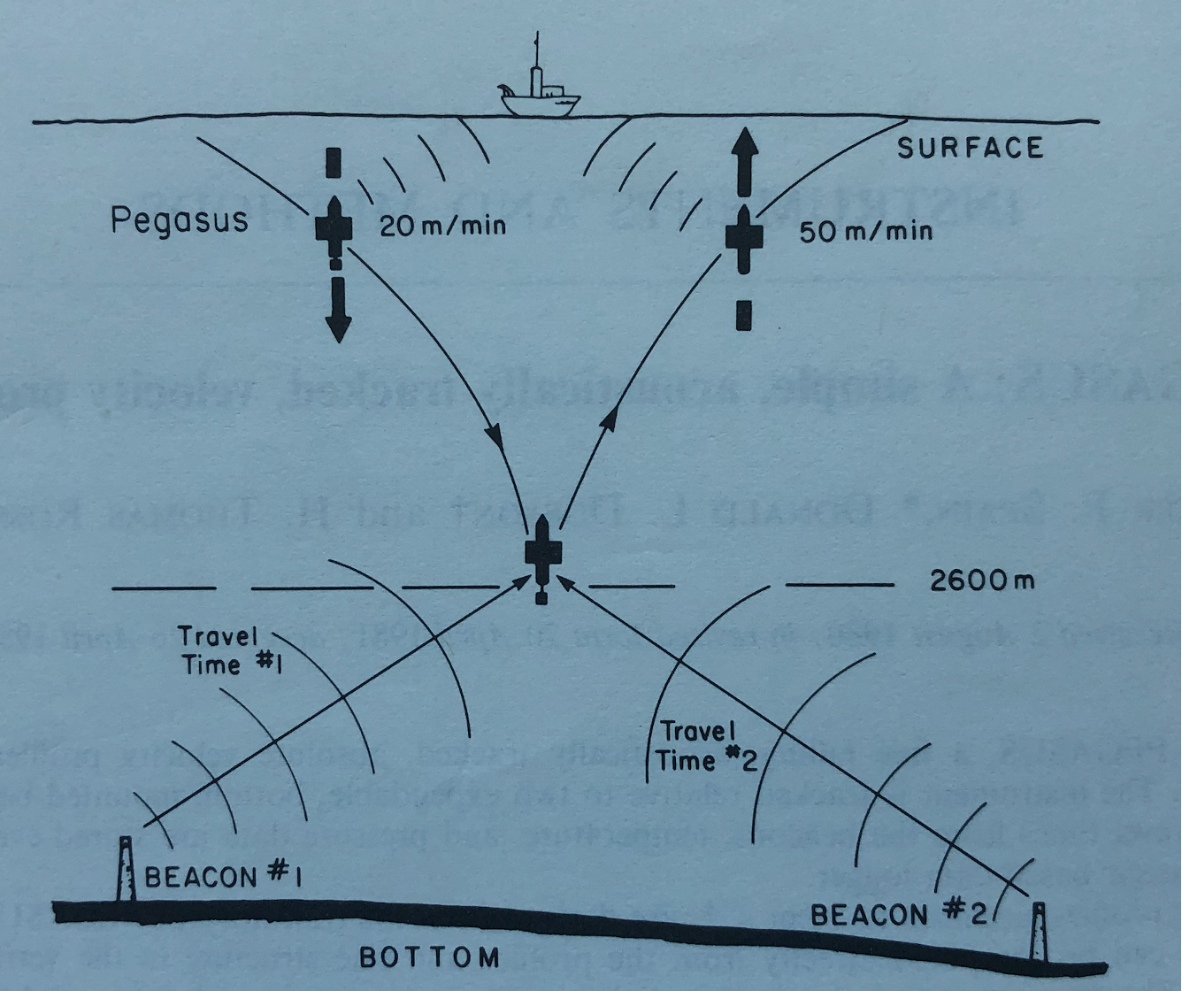 Spain, P.F., D.L. Dorson and H.T. Rossby. PEGASUS: A simple, acoustically tracked velocity profiler. Deep-Sea Res., 28, 1553-1567, 1981.
The Pegasus principle of operation is very straightforward: As it sinks and ascends it measures the travel time of acoustic pings from bottom beacons (or round-trip travel times to transponders). From those slant distances together with its depth (from pressure) we can determine from its trajectory the strength of the currents at all depths. Originally developed to study the Somali Current in 1979, it was used in a number of studies in the 1980s.
Pogo
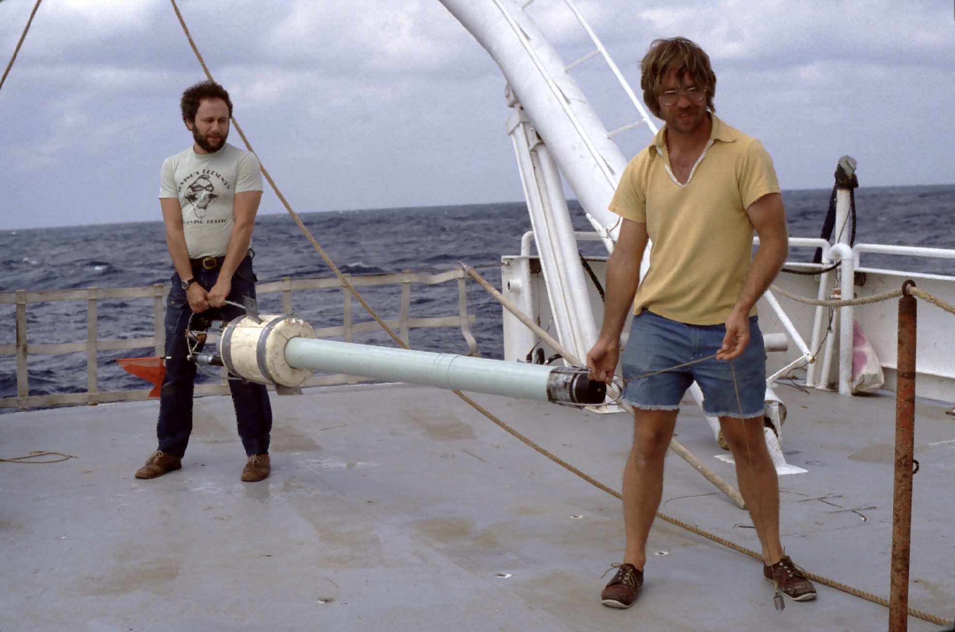
We designed Pogo to serve as a simple means to measure transport. Forgoing the details about the velocity profile, the function of this simple instrument is to sink to a predetermined depth, drop ballast and return to the surface to get the displacement vector at the surface between start and finish. That distance divided by elapsed time is vertically averaged velocity. Pogo consisted of an aluminum tube with a flasher, a radio beacon and a 12 kHz pinger. The arrival time of the pings gives us distance, and the radio (using a radio direction finder) or flasher (visually at night) gives us direction. When Pogo surfaces we immediately note the ship’s position and get a vector to it. The challenge was to be close by when it surfaced so we spot it right away to determine its position with a minimum of uncertainty. The photo shows Ed Levine and Terry Rago with the POGO. Small vanes (hard to see) on the white flotation collar causes Pogo to rotate as descends and ascends. This ensures that any tendency for it to kite (slip sideways) is averaged out. We later built a glass-pipe, more streamlined version of Pogo. The principle of operation is exactly the same as that of the Dropsonde used so successfully by Bill Richardson and Bill Schmitz in the Florida St in the 1960s.
# The SOFAR float
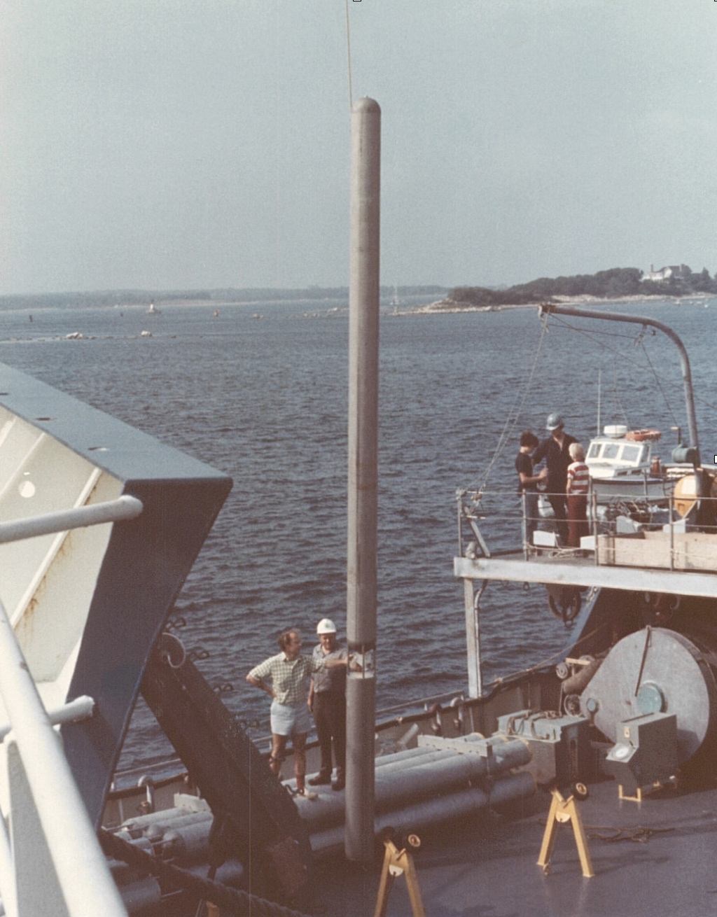
Photo of a polyMODE float being loaded on the RV Oceanus in spring 1978. The long tube provides the flotation for the batteries and electronics in it, the shorter tube rigidly attached at the lower end is the 250 Hz sound source. The floats were designed and built by Doug Webb (in the hard hat) at WHOI. Yours truly in shorts and long hair is standing next to him. Every 8 hours the floats emitted a 1.523 Hz swept FM signal over 80 seconds. The signals were received at SOFAR hydrophones I had instrumented at Bermuda, the Bahamas, Grand Turk (see blog) and Puerto Rico. The signals were recorded both digitally for later analysis and in visual form for real-time tracking of the floats. During the main field program an observer at the stations would phone in the arrival times so we could update the position of all floats daily; this proved to be very helpful, both in MODE and in polyMODE. Even though the aluminum tubes were much stiffer (less compressible) than water, we noticed that the earlier generation SOFAR floats (in MODE) slowly sank over time due to a very slight plastic creep of the metal. To prevent the polyMODE floats from sinking Doug mounted an insulated sacrificial zinc anode on the float. When the pressure exceeded a certain value, a relay would connect the anode to the aluminum so the zinc would corrode. With the loss of mass the float would return to its target depth, so clever!
# The SOFAR float tracking system
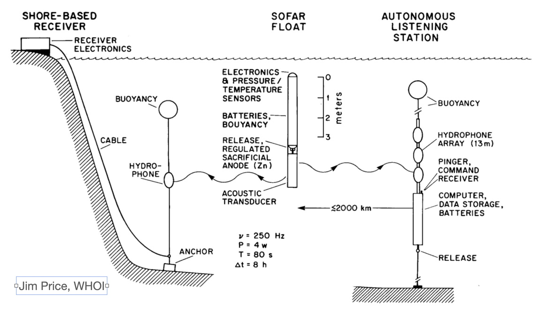
The transmissions from the floats were received at SOFAR hydrophones (placed at sound channel depth and permanently connected by underwater cable to shore) we had instrumented at Bermuda, Bahamas, Puerto Rico, and Grand Turk. The first three of these SOFAR hydrophones were part of the Atlantic Missile Impact Location System. When missiles (from Cape Canaveral) splashed down, they would release a tiny charge that would explode when it sank to SOFAR channel depth. The signal arrival times at the SOFAR hydrophones would be used to triangulate the splash down point. We installed the Grand Turk receiver to secure reliable acoustic coverage of the float transmissions. It proved to be a huge help. Read the Nov 9, 2023 blog post about the installation. It was an impressuve operaion.
These hydrophones suited us perfectly to track the floats and report to MODE and polyMODE scientists what the ocean was doing in real-time, a very exciting time! (And to detect failures, see the blog ‘Close call in MODE’) But these shore-based stations also restricted the geographical area where we could operate. To address this Al Bradley at WHOI developed the autonomous listening station that could be deployed anywhere. It was used in numerous studies by US and French oceanographers in the 1980s.
The RAFOS float
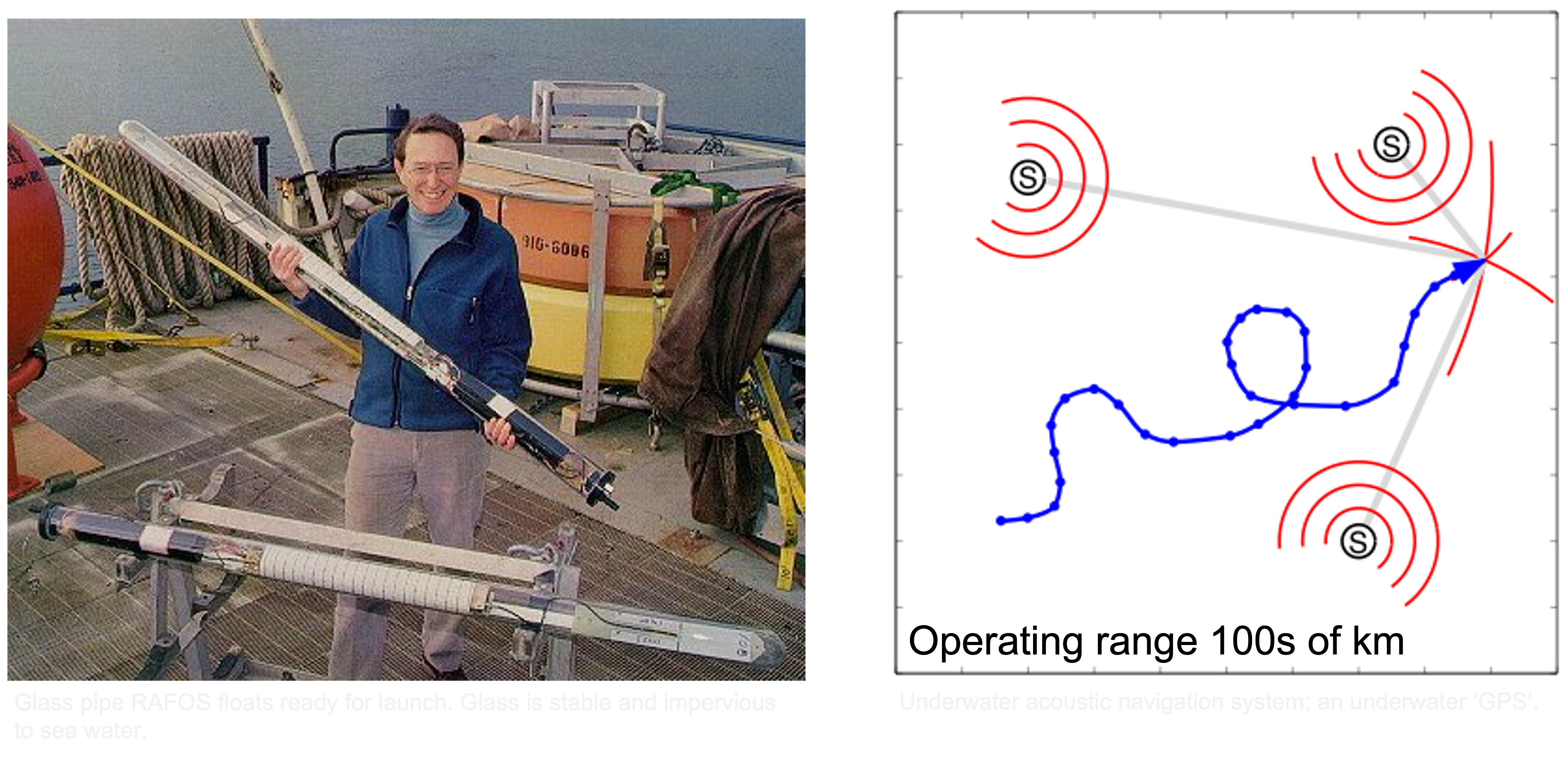
The RAFOS float principle of operation: As it drifts at depth it listens for and records the arrival times of precisely timed signals from moored sound sources. At end of mission the float surfaces and transmits to a satellite all data it has collected, pressure and temperature too. Knowing the speed of sound in sea water, the arrival times give us the float’s distance to the sources from which its position can be determined. Navigational accuracy ~3 km (depends on many factors).
The acoustic Doppler current profiler
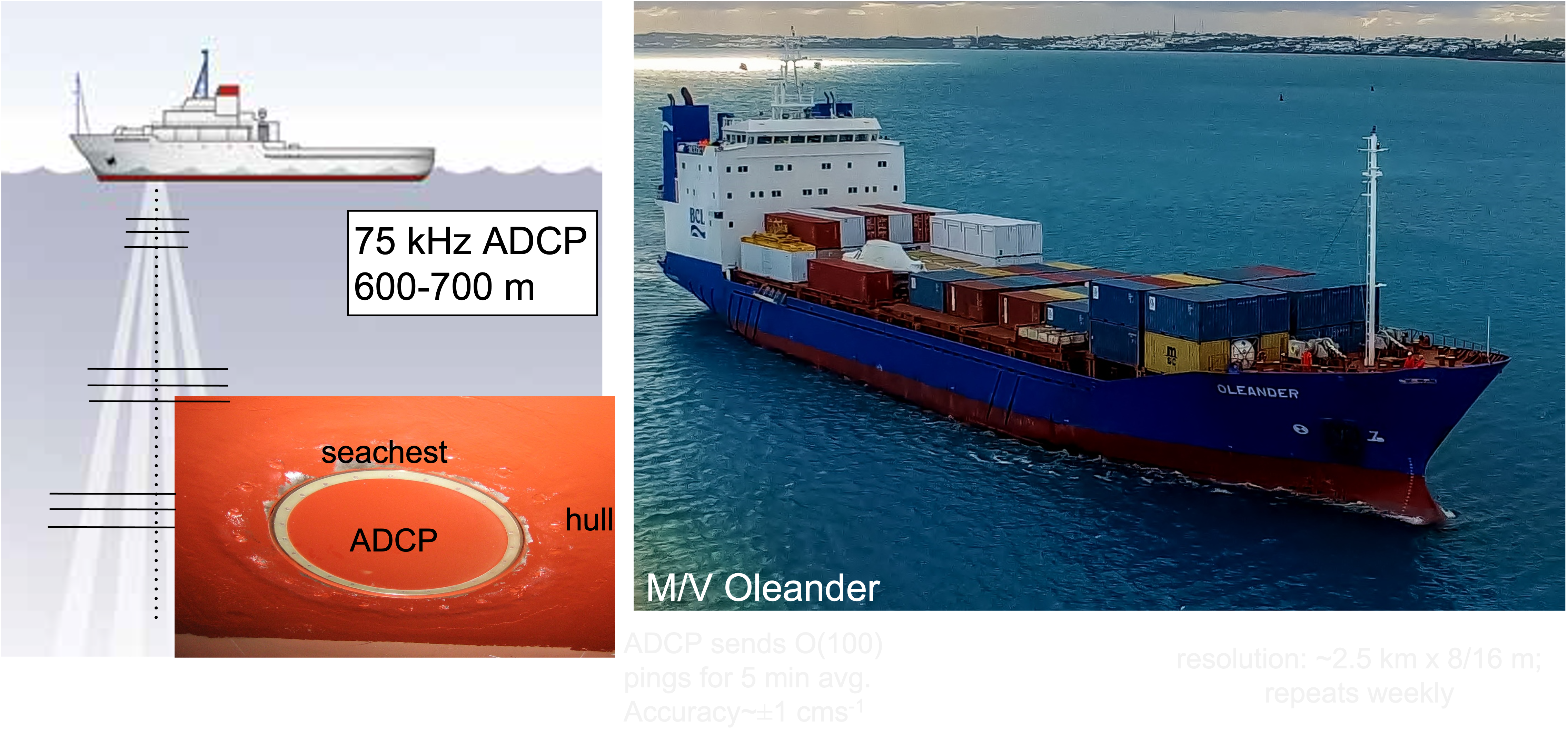
The ADCP transmits short acoustic pulses along four beams. The sound is reflected back at various depths primarily by zooplankton. The Doppler shifts gives velocity along each of the four beams. These can be transformed in u, v, w velocities relative to the ship. Water velocity is obtained after subtracting the ship’s velocity (from GPS). We have operated ADCPs on three ships for years and even decades (the Oleander).
Scanning the ocean with ADCPs

Starting in the early 1990s Charlie Flagg at Stony Brook University and I started a project to study the Gulf Stream and surrounding waters from the Oleander, a container vessel in weekly service between Bermuda and New Jersey. Mounted in the ship’s hull the ADCP profiles currents along the route.
In 1999 we teamed up with Prof. Martin Mork at the University of Bergen to operate an ADCP on the Nuka Arctica, a container vessel operating between Nuuk in Greenland and Aalborg in Denmark. In 2006 we installed an ADCP on the high-seas ferry Norröna. She operates out of the Faroes to Denmark and Iceland. We have learned so much from these operations.